VMware Standard, Distributed and Logical vSwitches Explained
Scroll Down
Introduction
In the world of virtualization and connectivity, the virtual switch is one of the most fundamental components, providing networking connectivity between virtual machines, along with connecting them to the physical world.
VMware provides 3 types of virtual switch, the virtual Standard Switch (vSS), the virtual Distributed Switch (vDS), and the Logical Switch.
VMware Networking Terminology
Before we begin, let us quickly go over the key VMware networking elements:
- VMKNIC - A virtual network interfaces, used by the VMKernel. This is used for traffic such as VMware management, vMotion, storage etc.
- VMNIC - The real physical interface on the ESX host.
- vPort - The virtual connection points upon the vSwitch. You can think of these as the virtual RJ-45 connections on the vSwitch.
- PortGroups - A port group is a configuration template that is applied to a group of network elements. A typical use of a port group is to apply a single VLAN to a group of VMs.
- Uplinks - A physical network adapter, used to bridge connectivity between the physical and virtual network. An uplink can only be assigned to a single vSwitch.
Below shows each of the components (described above):
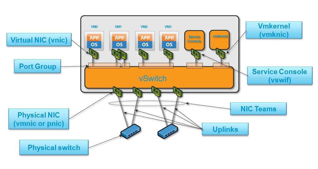
Figure 1 - Vmware network components. [1]
In addition, below is the output from an ESXi host with a standard switch configured. You can see the port groups, the VMNIC and also the VMKernel port used for management.
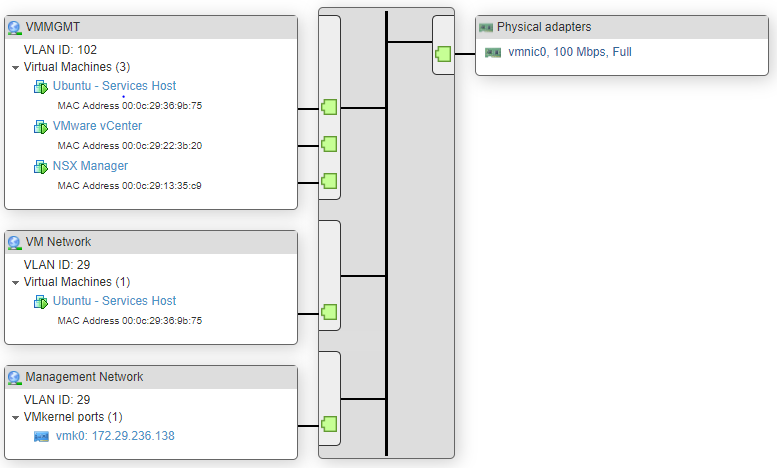
Figure 2 - vSS Example.
Standard vSwitch
A vSS (virtual Standard Switch), provides the basic functions of a physical switch, i.e it works at layer 2 and provides frame forwarding based upon MAC addresses. In addition, the vSS provides features such as NIC teaming, security and traffic shaping. Standard switches are configured at the host level, meaning that you must create and manage vSphere Standard Switches independently on each ESXi host.[2]
NIC Teaming
NIC teaming allows you to define how traffic is sent over multiple links. NIC teaming fall into two main categories - Network Failover Detection and Load Balancing.
Network Failover Detection
Network Failover Detection is used to define the mechanism that is used to signal to ESXi when traffic should failover to the other link. The options are:
- Link Status - If a link goes down, traffic is sent out of other port.
- Beacon Probing - Each VMNIC sends out beacon probes to each other. If an upstream network failure occurs then the vSwitch will not receive the expected probe and the VMNIC will be removed.
Load Balancing
The Load Balancing configuration defines how traffic is distributed across multiple active VMNICs. The options include:
- Originating Port ID - Each vPort is assigned a port ID. Each port ID is assigned to a VMNIC. Base on the port ID, traffic will be sent out of a different VMNIC. This is also known as - LoadBalance - SRCID.
- Source MAC Hash - Traffic is distributed to VMNICs based on the source MAC address. This is also known as - LoadBalance - SRCMAC.
- IP Hash - The source and destination IP is hashed. Each hash is assigned to a VMNIC. This allows a single VM to send traffic across multiple VMNICs.
Traffic Shaping
Allows you to set peak bandwidth and average bandwidth at a port group level. All VMs assigned to the port group will be limited to the bandwidth limitations defined.
Security
vSwitches provide a range of security configuration options. These security settings can be applied at either the virtual switch or port group level. Let us look at the different options:
- Forged Transmits - Allows MAC spoofing for outbound traffic. Therefore permitting a different MAC address to be sent by the VM other then what is defined to the VMs vNIC (based on the configuration of the VM). This option is enabled by default.
- MAC Address Changes - Allows MAC spoofing for inbound traffic. Therefore allowing a different MAC address to be received for a VM that is different to what is defined to the VMs vNIC (based on the configuration of the VM). This option is enabled by default.
- Promiscuous mode is a security policy which can be defined at the virtual switch or port group level in vSphere ESX/ESXi.[3] This option allows an interface to see ALL network traffic traversing the virtual switch. Promisc mode is disabled by default.
Spanning Tree
Let us take a moment to talk about spanning tree.
Because we know that a vSwitch will be connected to the end host (VM), VMware's implementation of the vSwitch results in there being no need for the Spanning Tree Protocol. As per VMware :
VMware infrastructure enforces a single-tier networking topology within the ESX Server. In other words, there is no way to interconnect multiple virtual switches; thus, the ESX network cannot be configured to introduce loops. Because of this, the vSwitch on the ESX host does not execute the Spanning Tree Protocol (STP).
For example, as the physical uplink, NICs are not bridged like a normal physical switch. Also, a (broadcast) frame will never travel through one uplink pNIC and then be sent out to the other uplink pNIC. Instead, it will only be forwarded to the VMs of that port group.[4]
For a full breakdown and more details around this point, please see http://blog.ipspace.net/2010/11/vmware-virtual-switch-no-need-for-stp.html
Distributed vSwitch
Distributed vSwitches bring the key advantage of scalability, whilst also providing a number of additional features to the standard virtual switch.
Whereas standard vSwitches requires the configuration to be applied to each ESXi host, distributed switches split the management plane and data plane functions, allowing the configuration to be defined within vCenter and pushed out to each of the ESXi hosts.
This provides the advantage of only having to define the uplinks, port group, and vlans just once (within the vCenter), therefore reducing time and human error; negating the need to apply the configuration one by one to each ESXi host.
vDS brings the following terminology:
- dvPortGroup - The distributed port group applied to each host.
- dvUplinkPortGroup - The distributed port group applied to the distributed uplinks, applied to each host.
- dvUplink - The distributed uplinks applied to each host.
Note: the vDS model operates based on hidden switches being deployed to each ESXi host. vCenter then configures these switches against the vDS configuration applied.
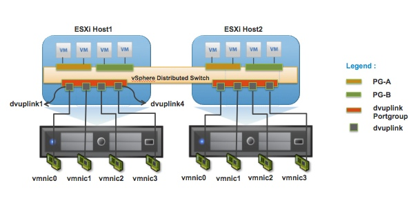
Figure 3 - vDS components. [5]
Features
In addition to the features provided by the standard vSwitch, distributed vSwitches also adds the following key features:
- Private VLANs - Allows the isolation of traffic within a single VLAN.
- NIC Teaming (Physical NIC Load) - Each VM sends traffic out of a different VMNIC. However at the point single VMNIC reaches a given level, VMs are migrated to over VMNICs to ensure that the traffic is equally distributed across each of the VMNICs. This feature is also known as - LBT/Route based on physical NIC Load.
- LACP - Allows you to aggregate both VMNICs together, into one logical link. LACP provides a huge list of balancing methods. Such as:
- Network I/O Control (NIOC) - Network I/O Control provides the ability to reserve bandwidth for system traffic based on the capacity of the physical adapters on a host. It enables fine-grained resource control at the VM network adapter level similar to the model that you use for allocating CPU and memory resources.[6]
- Network Health Check - Allows the host to detect if there are any misconfiguration between the physical switch and the vSwitch/port group.
- Port Mirroring - Provides the ability to mirror (known as dvMirror) the traffic from a vNIC and send to a network monitoring device. vDS provides the ability to (based on the Cisco SPAN convention):
- SPAN - Send the packet to another port upon the same switch.
- RSPAN - Send the packet across the network within a defined RSPAN VLAN.
- ERSPAN - Send the mirrored packet across the network within a GRE encapsulated packet.
Logical vSwitch
A logical switch is a switch, which runs on top of a vDS (via a kernel module) to provide VXLAN capability. VXLAN provides tunneled transport over a physical network (also known as the underlay) via UDP port 8472. This tunneling, therefore, negates the need to reconfigure the physical network each time a new segment is required.
A VTEP (a VMkernel port) is assigned to each physical adapter. The VTEP is responsible for the encapsulation and decapsulation of traffic to and from the VXLAN tunnel.
With this encapsulation, an additional 50 bytes of overhead is added, pushing the minimum MTU required for VXLAN traffic to 1600 bytes.
Each VXLAN segment is defined with a VNI (VXLAN Network Identifiers), similar to a VLAN IDs that are added within the VXLAN header at the point of encapsulation. However, the key advantage to VNIs over VLANs is that you can have up to 16 million IDs! It is also worth noting that VNIs start at 5000 to prevent any confusion to VLAN ID assignments.
Transport Zones
A Transport Zone defines a collection of ESXi hosts that can communicate with each other across a physical network infrastructure.
This communication happens over one or more interfaces defined as VXLAN Tunnel Endpoints (VTEPs).[7]
Universal Logical Switches
In a cross-vCenter NSX deployment, universal logical switches can be configured to span all vCenters. Universal logical switches (ULR) also require a universal control cluster (UCC)
Replication Modes
When BUM (broadcast, unknown unicast and multicast) traffic is sent out from a VM, the source VTEP must be replicated this traffic out to the other VTEPs via VXLAN encapsulation.
NSX provides 3 modes of replication - Multicast, Unicast and Hybrid.
- Multicast - IGMP (L2) and PIM (L3) are configured upon the physical switches, to ensure the source VTEP sends traffic only once out to the multicast group.
- Unicast - Source VTEP sends traffic (out multiple times) to all local VTEPs via unicast. Traffic is also sent to proxy VTEPs (UTEP's) via unicast. They sit in remote VXLAN segments, and once they receive traffic, they forward it on via unicast to its own local VXLANs.
- Hybrid - IGMP is used at L2 for multicast forwarding. Traffic between local and remote VTEPs use a proxy VTEP called an MTEP. The MTEP receives the traffic via unicast and then sends it out to the multicast group.
Additional Links
References
"What is vNIC, VMKNIC, PortGroups, Uplink Ports, vPorts ... - GoVMLab." 16 Mar. 2016, http://www.govmlab.com/what-is-vnic-vmknic-portgroups-uplink-ports-vports-and-vmxnet3/. Accessed 1 Apr. 2018. ↩︎
"Standard switch explained | VMware ESXi - Geek University." http://geek-university.com/vmware-esxi/standard-switch-explained/. Accessed 31 Mar. 2018. ↩︎
"How promiscuous mode works at the virtual switch and port group levels." 17 Jul. 2017, https://kb.vmware.com/s/article/1002934. Accessed 1 Apr. 2018. ↩︎
"How promiscuous mode works at the virtual switch and port group levels." 17 Jul. 2017, https://kb.vmware.com/s/article/1002934. Accessed 1 Apr. 2018. ↩︎
"VDS Best Practices - Virtual and Physical Switch ... - VMware Blogs." 22 Nov. 2011, https://blogs.vmware.com/vsphere/2011/11/vds-best-practices-virtual-and-physical-switch-parameters.html. Accessed 10 Apr. 2018. ↩︎
"About vSphere Network I/O Control Version 3 - VMware Docs." 4 Nov. 2014, https://docs.vmware.com/en/VMware-vSphere/6.0/com.vmware.vsphere.networking.doc/GUID-98E0B3C2-52A7-4CAB-A839-4DA82A9F6D3A.html. Accessed 10 Apr. 2018. ↩︎
"VMware NSX Network Virtualization Design Guide." https://www.vmware.com/files/kr/pdf/products/nsx/vmw-nsx-network-virtualization-design-guide.pdf. Accessed 8 Apr. 2018. ↩︎