
... Here we are, at the final part of our series on how to install a virtual NSX lab.
With our vSphere infra, NSX Manager, and NSX Control Cluster installed, we can now move to the NSX dataplane.
NSX Dataplane
The process for data plane installation is based upon the NSX Manager deploying VXLAN VIBs to each of the ESXi hosts. This results in a VXLAN VTEP (a VMKernel interface) being installed onto each host.
The IP/VLANs that will be used are:
| Cluster | vDS | VLAN | Network | IP Range |
|---|---|---|---|---|
| NFV-Resource | vDS-Resource | 113 | 172.29.113.0/24 | 172.29.113.100-150 |
| NFV-Edge | vDS-Edge | 123 | 172.29.123.0/24 | 172.29.123.100-150 |
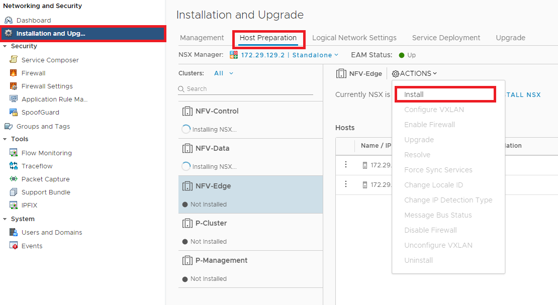
Figure 1 - Starting the VXLAN install.
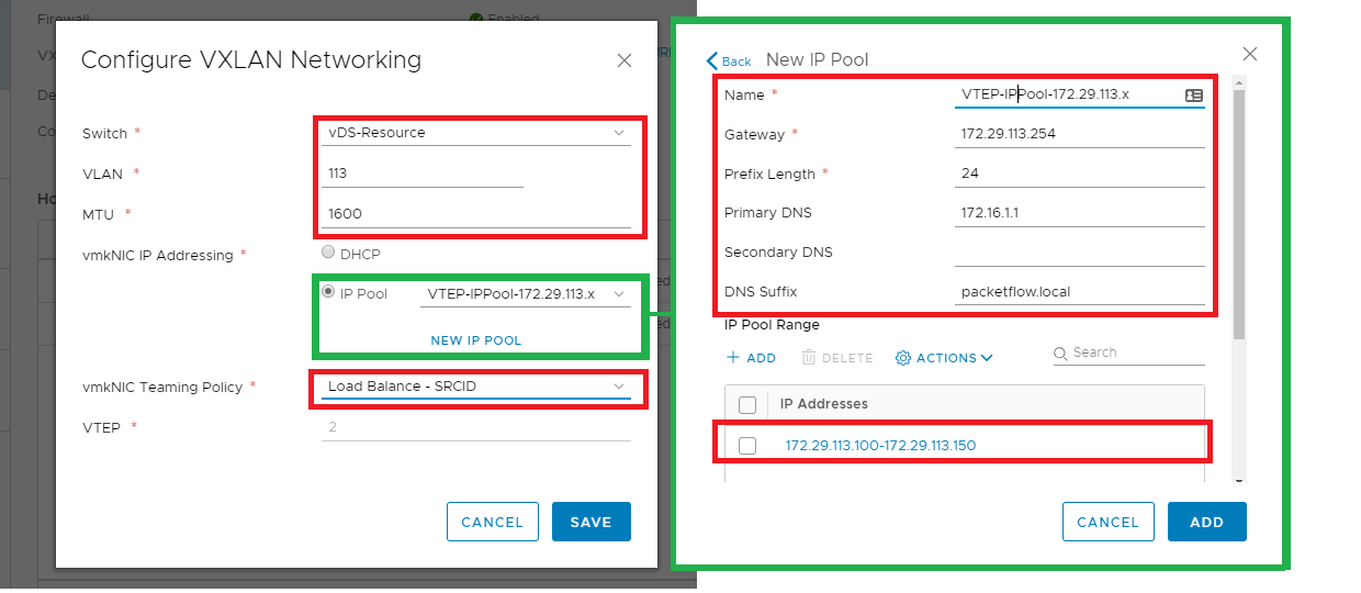
Figure 2 - Configuring VXLAN VTEPs.
Verify
Once VXLAN is installed we can verify that the VTEP is present via the following command:
[root@esxi001-nsxlab:~] esxcli network ip interface ipv4 get --netstack=vxlan
Name  IPv4 Address    IPv4 Netmask   IPv4 Broadcast  Address Type  Gateway  DHCP DNS
----  --------------  -------------  --------------  ------------  -------  --------
vmk1  172.29.113.104  255.255.255.0  172.29.113.255  STATIC        0.0.0.0     false
vmk2  172.29.113.106  255.255.255.0  172.29.113.255  STATIC        0.0.0.0     false
From the output above we can see that 2 VTEPs are shown. This is expected due to there being 2 physical uplinks from each ESXi host.
Final Verification
Now that the management, control, and data plane is installed we can run a final verification.
Our final verification will test connectivity between clusters using a logical switch (aka VXLAN tunnel).
Create VMs
2 VMs are deployed - 1 upon the NFV-Control cluster and 1 upon the NFV-Edge (as shown below).
Note: In essence, based on the NFV 3 pod design VMs would only be deployed within the resource pod and not upon the Edge pod. But for sake of testing an L2 network using our overlay (VXLAN) across an underlay spanning different L3 networks, this placement is fine.
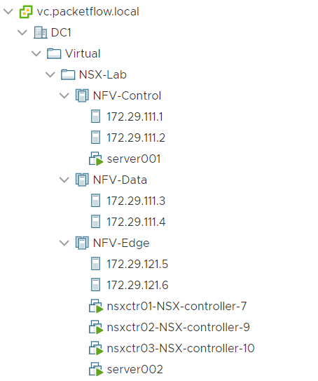
Figure 3 - VM layout across clusters.
Define VNI Range
The Segment IDs are defined, aka VNIs are configured. Like so,
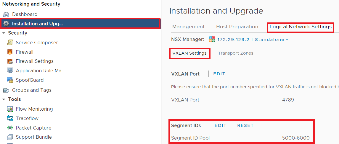
Figure 4 - Define the VNI range.
Create Transport Zone
The Transport Zone defines which clusters the logical switch will span. Below shows the steps:
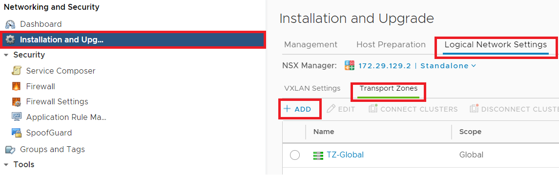
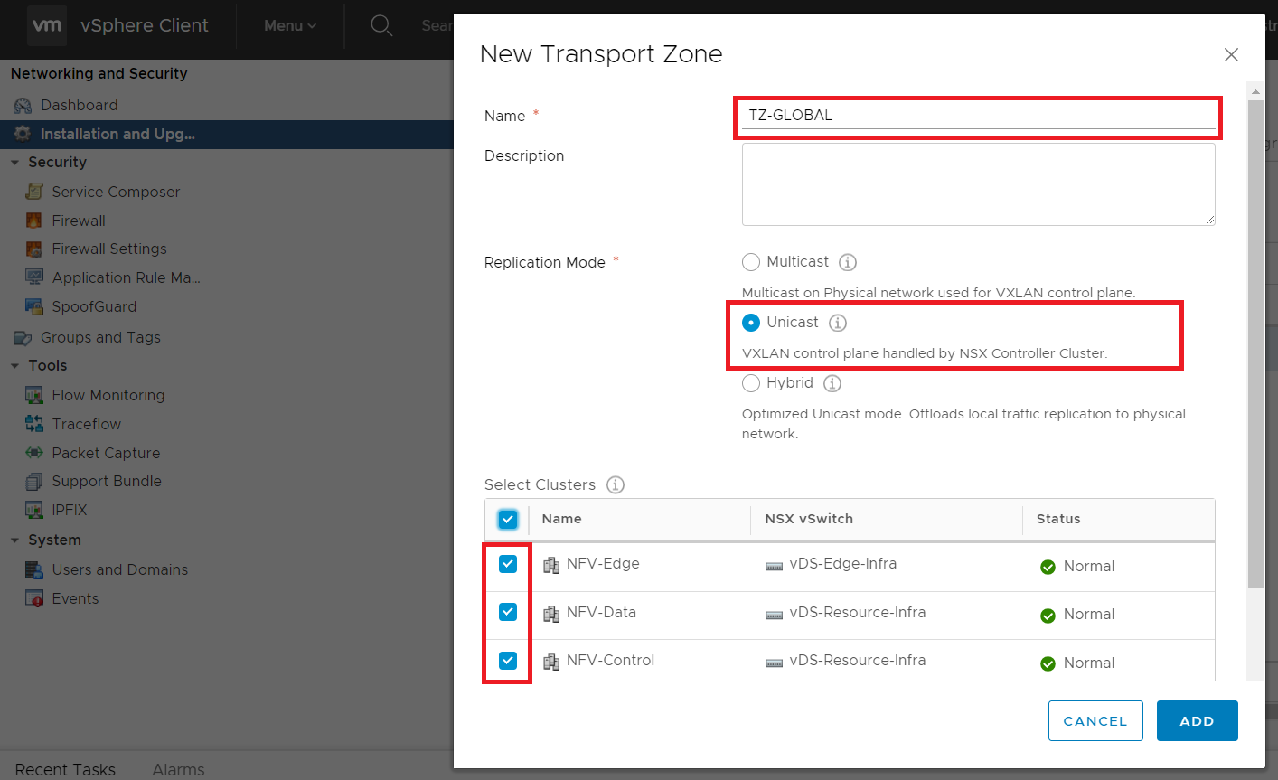
Figure 5 and 6 - Create transport zone.
Create Logical Switch
Next the logical switch is created (shown below), with,
- the previously created transport zone being applied.
Enable IP Discoverybeing enabled.
Note: The Enable IP Discovery option aids with reducing ARP broadcasts. By the NSX discovering the IPs/MAC address mappings from each host. At the point, the VTEP sees an ARP broadcast it intercepts, queries the NSX controller, and then responds to the ARP request locally.
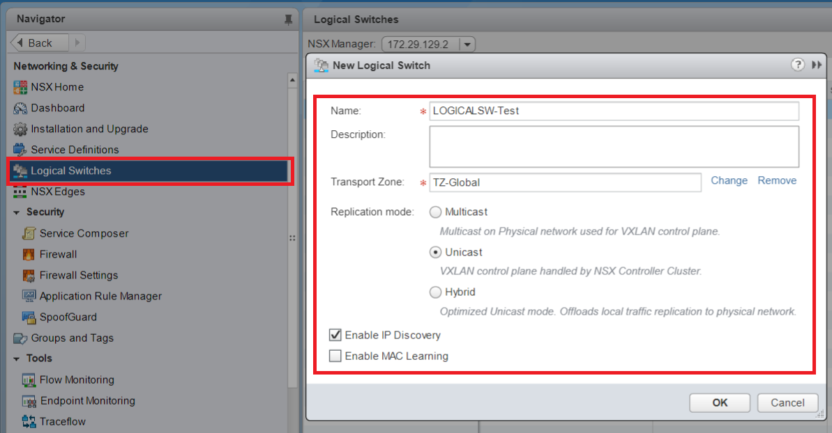
Figure 7 - Create logical switch.
Assign VMs to Logical Switch
Go into each VM, and assign the Network Adapter to the previously created logical switch.
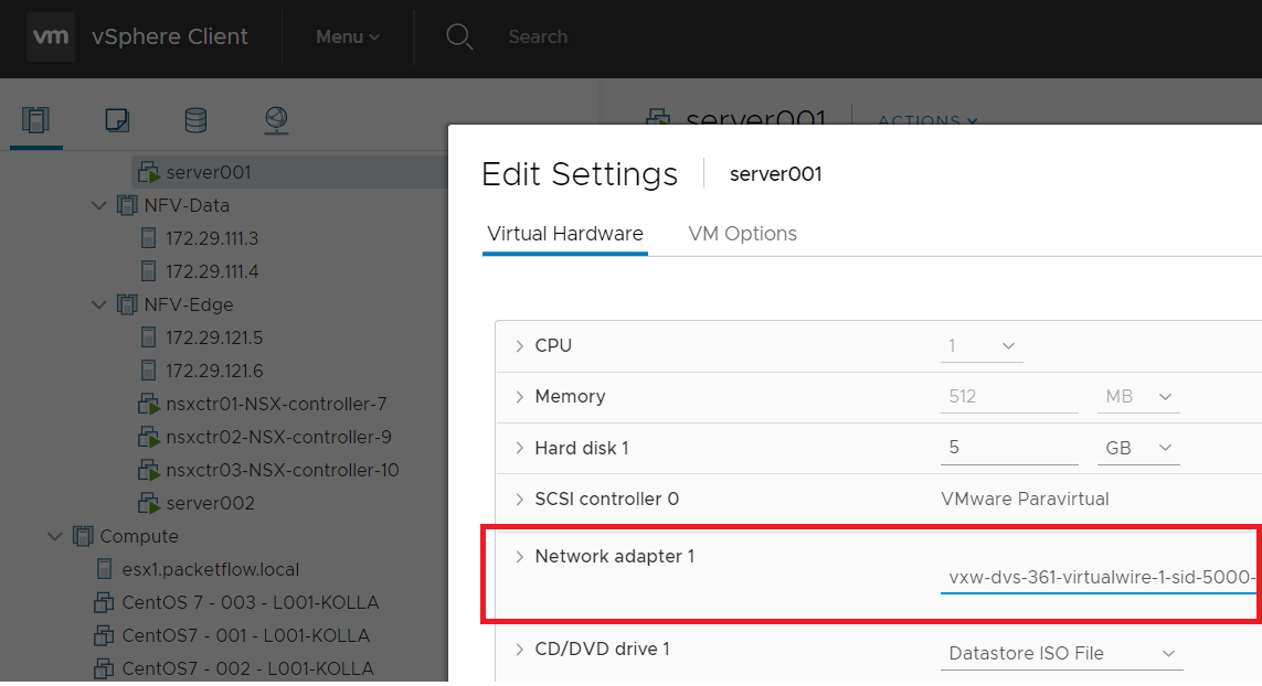
Figure 8 - Assign VM to logical switch.
Configure VM IP's
Go into each VM and configure eth0 with IPs in the same network. I.e
- Server001 -
ifconfig eth0 192.168.1.10/24 up - Server002 -
ifconfig eth0 192.168.1.11/24 up
Ping
With all the steps now done, we can now issue a ping on each VM, and connectivity should be seen. If your pings are successful - good work
- you now have traffic running across your logical switch aka your VXLAN overlay.
Outro
That concludes are series around installing a virtual NSX lab and we hope you have enjoyed the series.