vSAN Network Design - Key Points
Scroll Down
Introduction
This article provides a summary to some of the key points around vSAN network design.
For full details around vSAN network design please review https://storagehub.vmware.com/export_to_pdf/vmware-r-vsan-tm-network-design.
What is vSAN?
vSAN is a hypervisor-converged, software-defined storage solution for the software-defined data centre. It is the first policy-driven storage product designed for VMware vSphere® environments that simplifies and streamlines storage provisioning and management.[1]
Or in other words: Disks on multiple hosts are added to a pool. The pool of disks is then combined to form a large shared datastore, that each host with the relating cluster can access.
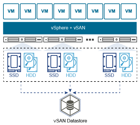
Figure 1: vSAN Highlevel
Multicast Discovery
With vSAN release version 6.6, the requirement for IP multicast is removed from vSAN. Since vSAN 5.5, CMMDS used multicast as a discovery
protocol to find all other nodes trying to join a vSAN cluster with the same sub-cluster UUID. vSAN 6.6 now communicates using unicast for CMMDS (Clustering Monitoring, Membership, and Directory Services) updates.[2]
Note: vCloud NFV 2.0.1 includes vSAN 6.6.1 as part of the bundle.[3]
Recommendations
Jumbo Frames
vSAN fully supports Jumbo Frames (9000 MTU) and can reduce CPU utilization and improve throughput.
NIC Speeds
Virtual SAN requires a 1GbE network at the minimum. As a best practice, VMware strongly recommends 10GbE network for Virtual SAN to avoid the possibility of the network being the bottleneck.
NIC Teaming
NIC teaming is used to provide a) high availability and/or b) traffic load balancing across multiple links. There are a number of options available with regards to NIC teaming, however, throughout the various options, my recommendation is based on selecting a NIC teaming method that will provide active/active load sharing across both links.
To achieve this it is recommended to configure LACP on the vDS uplinks.
LACP (Link Aggregation Control Protocol) is an open standards protocol (IEEE802.3ad) that allows multiple physical interfaces to be aggregated into one logical link.
Furthermore,
- The load balancing method: Source and destination IP addresses, TCP/UDP port and VLAN is used to ensure that traffic is sent across both links in a distributed manner.
- The LACP mode - Active - is configured on both sides (vDS and physical switch).
- When Active mode is configured the switch tries to actively negotiate and form LACP with its neighbour.
- This configuration results in only a single VMkernel NIC for vSAN (on each ESXi host).
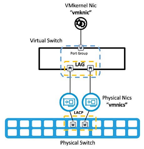
Figure 2: LACP Uplinks.
The key benefits to this NIC teaming option are:
- improves performance and bandwidth: Traffic is balanced across both vDS uplinks on each ESXi host. Therefore using the aggregated bandwidth and networking buffers.
- Network adapter redundancy: If a NIC fails and the link-state goes down, the remaining NICs in the team continue to pass traffic.
- Rebalancing of traffic after failures is fast and automatic.
References
"VMware® vSAN™ Network Design - StorageHub." 19 Apr. 2017, https://storagehub.vmware.com/export_to_pdf/vmware-r-vsan-tm-network-design. Accessed 19 Sep. 2018. ↩︎
"VMware® vSAN™ Network Design - StorageHub." 19 Apr. 2017, https://storagehub.vmware.com/export_to_pdf/vmware-r-vsan-tm-network-design. Accessed 19 Sep. 2018. ↩︎
"VMware vCloud NFV 2.0.1 Release Notes - VMware Docs." 26 Jun. 2018, https://docs.vmware.com/en/VMware-vCloud-NFV/2.0/rn/VMware-vCloud-NFV-201-Release-Notes.html. Accessed 19 Sep. 2018. ↩︎