
What is a Port-Channel?
Before we dive into vPC it is important to quickly review Port-Channels.
A Port-Channel is a technology that provides a way to aggregate (bond) multiple interfaces together. Traffic is then loadbalanced across each of the connections. Port-Channels provide 3 key benefits,
- Redundancy - Should one of the interfaces fail traffic is sent over the remaining links.
- Bandwidth - Increase in bandwidth due to bundling multiple interfaces together. Traffic is then loadbalanced across each of the links within the 'bundle'.
- Spanning Tree - Port-Channels are seen as a single switchport by Spanning-Tree protocols.
Though Port-Channels are great, the problem is that all links within the "bundle" must be connected to the same switch.
What is vPC?
vPC (Virtual Port-Channel), also known as multichassis EtherChannel (MEC) is a feature on the Cisco Nexus switches that provides the ability to configure a Port-Channel across multiple switches (i.e. vPC peers).
vPC is similar to Virtual Switch System (VSS) on the Catalyst 6500s. However, the key difference between vPC and VSS is that VSS creates a single logical switch. This results in a single control plane for both management and configuration purposes. Whereas with vPC each switch is managed and configured independently.
It is important to remember that with vPC both switches are managed independently. This means you will need to create and permit your VLANs on both Nexus switches.
Components
vPC consists of the following components. The example diagram below shows key vPC components,
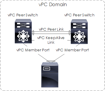
Figure 1: vPC Components.
Let’s look at each of the vPC components,
- vPC Domain - Includes the vPC Peers, KeepAlive Links and the Port-Channels that use the vPC technology.
- vPC Peer Switch - The other switch within the vPC domain. Each switch is connected via the vPC peer link. It's also worth noting that one device is selected as primary and the other secondary.
- vPC Member Port - Ports included within the vPCs.
- vPC Peer-Keepalive Link - Connects both vPC peer switches and carries monitoring traffic to/from each peer switch. Monitoring is performed to ensure the switches are both operational and running vPC.
- vPC Peer Link - Connects both vPC peer switches and carries BPDUs, HSRPs, and MAC addresses to its vPC peer. In the event of vPC member port failure, it also carries unicast traffic to the peer switch.
- Orphan Port - An orphan port is a port that is configured with a vPC VLAN (i.e a VLAN that is carried over the vPC peer link) and is not configured as a vPC member port.
Orphan Ports
As previously mentioned an orphan port is a port that is not configured as a vPC member port and is configured with a vPC VLAN (i.e the VLAN is carried over the vPC peer link).
Here lies the issue. When the vPC peer-link goes down only the vPC member ports are shut down, i.e orphan ports remain up. Because of this, devices that are configured with NIC teaming or in an active/standby setup and connected to both switches will not correctly failover. In order to ensure the orphan port is brought down correctly the interface command orphan port suspend is used.
For single devices with active/standby links, it is recommended to port-channel ports across both switches and configure both ports as vPC member ports.
Peer Link
The vPC peer-link is the most important component within the vPC domain. Just as we mentioned, should a member port fail then the peer-link is used to send unicast traffic to the peer.
Consider the following,
- Traffic arrives at Server1 destined to Server2.
- Traffic is sent to Switch1 via Po30.
- The packets are unable to take the Po40 path on Switch1 as the member port is down.
- Instead, the packets are sent over to the peer switch via the vPC peer link and sent to Server2 via Po40.
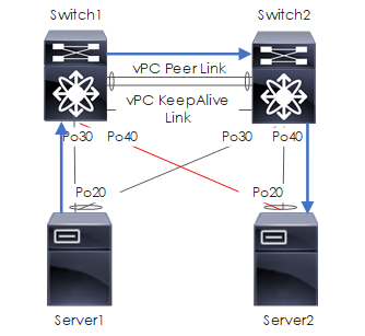
Figure 2: PeerLink Scenario
Configuration
Below shows the necessary configuration. This configuration is applied to both switches. However please ensure to amend the IP addresses accordingly.
Additionally, please note that within this example the following port-channels will be used for the peer-link and keepalive.
- Po300 - vPC PeerLink
- Po400 - vPC KeepAlive
Create vPC VRF
vrf context VPC_KEEPALIVE
Enable vPC
feature vpc
Create vPC Domain
vpc domain 105
 peer-keepalive destination 10.1.1.1 source 10.1.1.2 vrf VPC_KEEPALIVE
Create vPC Peerlink
interface Ethernet1/37
 description vPC Peerlink
 switchport mode trunk
 channel-group 300 mode active

interface Ethernet1/38
 description vPC Peerlink
 switchport mode trunk
 channel-group 300 mode active

interface port-channel300
 description vPC Peerlink
 vpc peer-link
Create vPC KeepAlive
interface Ethernet1/47
 description vPC Keepalive
 no switchport
 channel-group 400 mode active

interface Ethernet1/48
 description vPC Keepalive
 no switchport
 channel-group 400 mode active

interface port-channel400
 description vPC Keepalive
 vrf member VPC_KEEPALIVE
 no switchport
 ip address 10.1.1.[1-2]/30
Create vPC Member Port
Finally, we create a Virtual Port-Channel, by creating a Port-Channel on each switch. The Port-Channel config is standard but we also include the command vpc 30. This command is added to both Port-Channels on both switches.
# switch 1
interface gi0/30
 channel-group 30

interface po30
 vpc 30

# switch 2
interface gi0/30
  channel-group 30

interface po30
  vpc 30
Once complete, check the status of vPC by using the commands below.
Show/Debug Commands
Brief
The first place to check to see an overview of the vPC setup and how it is running is via the command show vpc brief.
switch2# show vpc brief
Legend:
            	(*) - local vPC is down, forwarding via vPC peer-link

vPC domain id                 	: 100
Peer status                   	: peer adjacency formed ok
vPC keep-alive status         	: peer is alive
Configuration consistency status  : success
Per-vlan consistency status   	: success
Type-2 consistency status     	: success
vPC role                      	: secondary
Number of vPCs configured     	: 2
Peer Gateway                  	: Enabled
Peer gateway excluded VLANs   	: -
Dual-active excluded VLANs    	: -
Graceful Consistency Check    	: Enabled
Auto-recovery status          	: Enabled (timeout = 240 seconds)

vPC Peer-link status
---------------------------------------------------------------------
id   Port   Status Active vlans
--   ----   ------ --------------------------------------------------
1	Po2	up 	1,9,1120,4093

vPC status
----------------------------------------------------------------------------
id 	Port    	Status Consistency Reason                 	Active vlans
------ ----------- ------ ----------- -------------------------- -----------
30	 Po30 	   up 	success 	success                	1120
40	 Po40   	 up 	success 	success                	1120
Orphan Ports
To confirm which ports are orphan ports the following command is used,
switch1# sh vpc orphan-ports
Note:
--------::Going through port database. Please be patient.::--------

VLAN    Orphan Ports
------- -------------------------
400     Eth1/1, Eth1/2, Eth1/3, Eth1/4, Eth1/5, Eth1/6
Consistency
To show the consistency across vPC peers the show vpc consistency-parameter … is used.
switch2# sh vpc consistency-parameters vpc 30

	Legend:
    	Type 1 : vPC will be suspended in case of mismatch

Name                    	Type  Local Value        	Peer Value
-------------           	----  ---------------------- -----------------------
Shut Lan                	1 	No                 	No
STP Port Type           	1 	Edge Trunk Port    	Edge Trunk Port
STP Port Guard          	1 	None               	None
STP MST Simulate PVST   	1 	Default            	Default
lag-id                  	1 	[(7f9b,            	[(7f9b,
                              	0-2-4-ef-be-69, 801b, 0-2-4-ef-be-69, 801b,
                               	0, 0), (8000,      	0, 0), (8000,
                              	f4-cf-e2-0-1e-76, 2,   f4-cf-e2-0-1e-76, 2,
                              	0, 0)]             	0, 0)]
mode                    	1 	active             	active
Speed                   	1 	10 Gb/s            	10 Gb/s
Duplex                  	1 	full               	full
Port Mode               	1 	trunk              	trunk
Native Vlan             	1 	1                  	1
MTU                     	1 	1500               	1500
Admin port mode         	1
vPC card type           	1 	Empty              	Empty
Allowed VLANs           	- 	2-8,10-4092,4094   	2-8,10-4092,4094
Local suspended VLANs   	- 	-                  	-
Peer-KeepAlive
Finally to check the status of the vPC keepalive the command show vpc peer-keepalive is used.
switch2# show vpc peer-keepalive

vPC keep-alive status           : peer is alive
--Peer is alive for         	: (2300862) seconds, (249) msec
--Send status               	: Success
--Last send at              	: 2015.03.19 06:52:22 954 ms
--Sent on interface         	: Po400
--Receive status            	: Success
--Last receive at           	: 2015.03.19 06:52:22 955 ms
--Received on interface     	: Po400
--Last update from peer     	: (0) seconds, (219) msec

vPC Keep-alive parameters
--Destination               	: 10.1.1.1
--Keepalive interval        	: 1000 msec
--Keepalive timeout         	: 5 seconds
--Keepalive hold timeout    	: 3 seconds
--Keepalive vrf             	: VPC_KEEPALIVE
--Keepalive udp port        	: 3200
--Keepalive tos             	: 192
 Rick Donato